Country and language selection
Your country: Korea
Your language: English

Do your AHU fans really perform as promised?

Why certifications matter in fan performance

Discover Fan Performance 360° now

Do you want to switch to your country version? Welcome to ZIEHL-ABEGG!
You are visiting our Website from Greece?

On the website for your region you will find information on the products relevant to you, contact details and news.

Unfortunately, there is no Greek language version of our website. However, you can stay on this page or contact our sales representative in Greece directly.

Fan Performance 360°

A Guide to Standards, Efficiency and Retrofit Solutions

A clear understanding of fan performance and its verification is essential for delivering reliable and energy-efficient air systems. This begins with fan aerodynamic performance test methods, which provide a consistent way to measure airflow, pressure, and efficiency under controlled conditions. Building on this, product certification plays a critical role in ensuring that the tested performance is independently validated and meets recognized industry standards, giving confidence to both designers and end users. 

Another key aspect is wire-to-air performance, which reflects the true overall efficiency of the fan system by considering all energy losses from the electrical input to the actual air output. In addition, modern applications increasingly require flexibility, particularly in AHU retrofit projects, where space constraints and existing system limitations demand adaptable solutions. 

Finally, understanding real duty point flexibility ensures that the selected fan can operate efficiently across varying conditions, rather than only at a single design point, supporting long-term performance and energy savings. 

Fan Aerodynamic Measurement Methods

According to ISO 5801

Aerodynamically, fans can be measured in different ways, as described in ISO 5801. The standard defines several measurement types depending on the inlet and outlet conditions of the fan.

Type A

Free Inlet and Free Outlet

Applicable to all fan types. Efficiency is calculated based solely on the static pressure increase, representing the basic air performance of the fan.

Type B

Free Inlet and Ducted Outlet

The outlet duct has the same cross-section as the fan housing. This configuration is commonly used for scroll housing fans, as it allows efficiency to be calculated using total pressure on the discharge side, often resulting in a higher efficiency value.

Type C

Ducted Inlet and Free Outlet

The inlet duct matches the fan housing cross-section. This setup is less common and typically used only for special axial fans.

Type D

Ducted Inlet and Ducted Outlet

Both inlet and outlet have the same cross-section as the fan housing. This type is frequently used for axial fans, especially high-pressure models where the discharge air velocity is high, leading to a higher total pressure increase and improved total efficiency.

Importance of Selecting the Correct Measurement Type

It is essencial to select the appropriate measurement type according to ISO 5801 when evaluating or comparing fan performance.
Recalculating performance data from one measurement type to another is not straightforward and requires additional measurement points.

  • When using Type A fan data to estimate performance for Types B to D, the calculated air performance and efficiency are typically lower than in actual operation. The fan may still handle the duty point but could be slightly oversized.
  • Conversely, if Type A installation performance is estimated based on Type B to D data, the calculated performance and efficiency will appear better than in reality. In this case, the fan may fail to meet the actual duty point due to inaccurate assumptions - especially regarding efficiency.

Why are Product Certifications important?

Different Levels of Certification

Across the Product Lifecycle

Test Rigs
Regular Certification

Fan Selection Software
Regular Certification

Production Processes
Regular Certification

Third-party certifications provide customers with greater confidence in a product´s performance, quality, and reliablity. They serve as an objective assurance that the product meets recognized industry standards.

Test Rigs - Regular Certification
(e.g., AHU manufacturer associations, Eurovent, AMCA, VDE, etc.)

  • Ensure that products are measured correctly in terms of air performance, electrical data, and acoustic characteristics.
  • Multiple test rigs are often required, as a single rig cannot cover a wide range of air performance accurately across all classes.

Fan Selection Software - Regular Certification
(e.g., AHU manufacturer associations, Eurovent, AMCA, VDE, etc.)

  • Ensures that fan performance calculations are accurate and reliable.
  • The highest standard is “wire-to-air” certified calculation, reflecting real operational efficiency.
  • Each fan series must be certified individually to account for specific aerodynamic and electrical characteristics.

Production Processes - Regular Certification
(e.g., ISO standards, AHU manufacturer associations, AMCA, etc.)

  • Guarantees consistent manufacturing quality and safe production processes, ensuring long-term product reliability and performance stability.

Why is wire to air performance data important?

“Wire-to-air performance data” are important because they show the total efficiency of a fan system - from the electrical power input (wire) to the actual air performance output (airflow and pressure).

Wire-to-air gives a true picture of energy consumption, which is crucial for system designers and end-users focused on total operating cost.

Shaft-to-Air is ideal for fan-to-fan comparisons, but it does not reflect motor or drive losses, so it can be misleading if used alone.

Aspect

Wire-to-Air Performance

Shaft-to-Air Performance

Definition

Total system efficiency from the electrical input at the power source (wire) to the air output (delivered airflow and pressure).

Efficiency from the fan shaft mechanical input to the air output.

Scope

Comprehensive - includes all losses: motor, VFD (if used), belt/drive, bearings, and fan.

Partial - includes only losses within the fan itself and any direct drive components.

Includes

Motor efficiency + VFD losses + Belt/gear losses + Fan aerodynamic losses.

Only the fan´s aerodynamic efficiency.

Measurement Point

Start point: electrical power at the wire terminal. 
End point: actual airflow and static pressure delivered.

Start point: mechanical power on the fan shaft.
End point: actual airflow and static pressure delivered.

Example Systems

EC plug fan with integrated electronics or belt-driven fan with separate motor and VFD.

Bare fan tested in a lab according to AMCA/ISO standards.

Industry Standards

AMCA 208 / ISO 13348 often specify wire-to-air for real-world efficiency ratings.

AMCA 210 / ISO 5801 typically specify shaft-to-air efficiency.

Real-World Relevance

Directly reflects what the customer pays for in electricity.

More theoretical - good for comparing fan design, but incomplete picture.

Accuracy for Energy Use

High - represents the real power draw from the electrical grid to the airflow delivered.

Limited - does not reflect actual energy usage, only aerodynamics fan efficiency.

Footprint & Space Planning

Reveals true efficiency of compact systems, like multiple EC fan arrays.

Does not highlight system-level advantages of modern designs.

Decision-Making

Useful for selecting high-efficiency systems and justifying premium options like EC fans.

May lead to wrong investment decisions if interpreted as total efficiency.

Flexibility in AHU Retrofit:

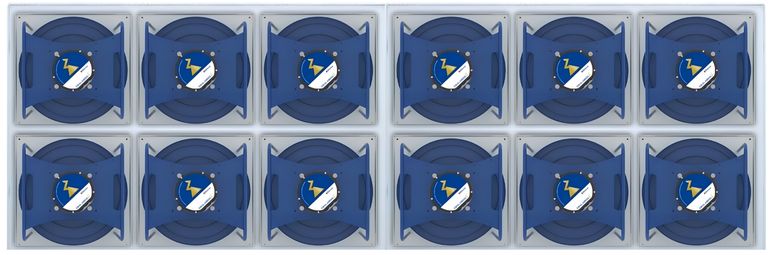
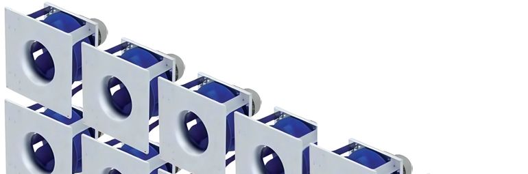
Multiple EC Fans vs. Single Axial Fan

Why Flexibility Matters in Retrofit

  • Limited space & difficult access
  • Existing ducting and structural constraints
  • Need for minimal downtime
  • Energy performance improvement
  • Integration with existing controls

Comparison Summary

Aspect

Wire-to-Air Performance

Shaft-to-Air Performance

Installation

Modular, easy to bring in sections though access doors

Large, needs major dismantling or crane

Space Adaptability

Flexible layout fits into light AHU space

Rigid layout, hard to adjust

Operation Flexibility

Individual speed control & staging

Single-speed or limited VFD control

Redundancy

One fan failure - others still run

Single failure - full system down

Energy Efficiency

Excellent at part-load; optimized airflow

Less efficient at partial load

Maintenance

Replace 1 fan while system runs

Requires full shutdown for service

Noise & Vibration

Low noise, balanced operation

Higher vibration & noise

Future Expandability

Add/remove fans as needed

Fixed capacity

Key Takeaways

  • Higher flexibility: fits existing AHU housing easily
  • Less downtime: modular installation and redundancy
  • Energy optimized: EC motor efficiency & staged control
  • Future-ready: adaptable for new airflow or system changes

Real duty points flexibility

Why can the real duty point differ from the design point?

Even if a fan is perfectly selected on paper, the actual operating point (airflow and static pressure) can differ from the design duty point due to several real-world factors:

1. System sesistance deviation

  • The calculated pressure drop of ductwork, filters, coils, and dampers is often based on estimates or clean conditions.
  • In reality, installation variances, bends, leakages, and additional fittings can increase or decrease total pressure loss.
  • As a result, the system curve shifts, moving the fan´s operating point along its performance curve.

2. Air density and environmental conditions

  • Fan performance depends on air density (which changes with temperature, altitude, or humidity).
  • A fan designed for standard (1.2 kg/m3 at 20°C) will perform differently in hot or humid environments.

3. Manufacturing tolerances and measurement errors

  • Both fan performance data and measurement instruments have tolerances (e.g. +/-5% flow, +/- 3% pressure).
  • These small variations can cause noticeable differences in real airflow and pressure.

4. Control system or speed setting differences

  • Incorrect VFD settings, EC fan control signals, or system balancing may cause fans to run at speeds other than the design intent.
  • Also, multiple fan systems (like EC grids) may not share load equally, altering the duty point.

5. System aging and operational conditions

  • Over time, filters clog, coils foul, or duct leak, changing the static pressure profile.
  • The fan´s performance then drifts away from the original design point.

In most AHU retrofit and variable-load AHU applications, multiple smaller EC fans are usually better than a single axial fan with a VFD - but it depends on priorities (efficiency, turndown, redundancy, space, cost, sound).

Why multiple EC fans often win

Better real-world (wire-to-air) efficiency across operating range
EC fans combine motor and electronics optimized for the fan - they keep efficiency high at partial speeds, where as a single AC motor and VFD often loses some efficiency at low speeds and though VFD and motor losses.

Wider, smoother turndown with good efficiency
You can stage fans (1, 2, 3…) and also vary each EC fan´s speed to match loads with fine granularity - giving very efficient performance from low to high loads.

Built-in redundancy / reliability
If one fan fails, the AHU can still operate (reduced capacity) - critical for comfort/critical spaces. With a single fan, failure would mean the whole AHU shutdown.

Easier matching to shifted system curve
Multiple fans let you change number of active fans and speeds to track the actual system curve after installation or as systems foul.

Improved part-load noise control
Running fewer fans at higher but efficient speed can sometimes be quieter than running one oversized fan at low inefficient speed - depends on fan selection and acoustics.

Smaller mechanical footprint and easier handling
Smaller fans are easier to install and replace; often fewer structural changes required.

Key design for multiple EC fans

(so they behave reliably and efficiently)

Fan selection and curve matching

  • Choose fans whose individual performance curves overlap so combined curve covers the system curve smoothly.
  • Check combined fan curves (parallel operation) and ensure no unstable regions (avoid big flat spots or points where small changes cause big shifts).
  • Request wire-to-air performance curves from suppliers (or test data) for realistic comparison.

Downloads & Contact

You need consultation?

Contact us!

Market Segment Management (Building)