Country and language selection
Your country: United Kingdom
Your language: English
Do you want to switch to your country version? Welcome to ZIEHL-ABEGG!
You are visiting our Website from Greece?

On the website for your region you will find information on the products relevant to you, contact details and news.

Unfortunately, there is no Greek language version of our website. However, you can stay on this page or contact our sales representative in Greece directly.

Pressure Definition

Pressure Definition: In physics, pressure generally refers to the quotient of a force acting perpendicularly on a surface. This results in the general pressure formula p = F / A

Types of pressure in ventilation technology
With regard to ventilation systems, different types of pressure are distinguished:

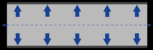
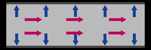
  • Static pressure is the pressure that a gaseous medium (e.g. air) exerts on the walls of the surrounding air duct perpendicular to the flow direction.
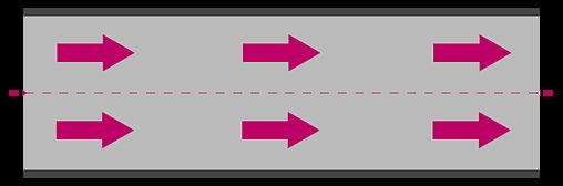
  • Dynamic pressure describes a form of kinetic energy, i.e., the energy of the flowing medium due to its movement. Thus, dynamic pressure generally acts in the direction of flow, parallel to the walls of the surrounding air duct.
  • Total pressure (= total pressure) is the sum of all static pressures and the dynamic pressure.

Pressures in ventilation systems can be positive on the discharge side or negative on the suction side of the fan. The delta Δp of the pressures between two measuring points is generally referred to as differential pressure or pressure difference.

The right pressure for everey application: ZIEHL-ABEGG fans impress with their Performance!

Pressure Units

The pressure unit commonly used for pressure in air technology is the Pascal (Pa). It describes the force in Newtons (N) acting perpendicularly on an area of 1 m2. Therefore, the pressure of 1 Pa results from the force of 1 Newton acting on an area of 1 m2: [p] = N/m2 = Pa.

An internationally common representation of pressure increase in design programs for air-conditioning systems is the static pressure in "pounds per square foot" (PSF for short).

In other areas, other pressure units are used in addition to Pascal, such as:

  • The Bar (1 bar = 100.000 Pa)
  • The Phsical Atmosphere(1 atm = 101.325 Pa)
  • The Pound-force per square inch (1 psi = 6.894,76 Pa)
  • The Inches of water gauge (1 inH2O = 248,8 Pa)
  • etc.

Calculating Pressure

If you want to calculate the pressure, there are different variants of the pressure formula (examples):

Static pressure ps as the quotient of a vertically acting force F on an area A:
 ps = F / A

The dynamic pressure pd is calculated from the gas density ρ (Rho) and the velocity c:
 pd = ρ / 2c2

The sum of all static and dynamic pressures of a system forms the total pressure pt (= total pressure, system pressure):
 pt = ps + pd

If the medium to be transported is a gas or gas mixture other than air, the product of the amount of substance n, the gas constant R and the temperature T is divided by the volume V:
 p = n * R * T / V

Alternatively, the pressure can be calculated from gas density ρ, gas constant R and temperature T:
 p = ρ / R * T

Dependencies Of Air Density

The pressure dependence of density in air conditioning systems when pressure differences occur is very small compared to atmospheric pressure and can be neglected. Therefore, air is assumed to be an incompressible medium (non-compressible) when designing air conditioning systems.

However, the temperature dependence of the density must be taken into account!

Altitude Formula

If an air-conditioning system is operated well above sea level, the air density must be calculated and taken into account. To calculate the pressure pH, the internationally recognized altitude formula (at a temperature of 0°C) is used, using the air pressure pa at sea level and the geodetic height Ha (represented with Euler's number e as a constant):
 pH = pa * e-Ha/7990

Bernoulli Formula & Bernoulli Effect

The Bernoulli formula states that the total pressure of an ideal flow, i.e. the sum of all static and dynamic pressures within a system, is constant at every point on the flow line.

From this assumption, the Bernoulli formula results:
 ρ / 2c2 + ps =constant.

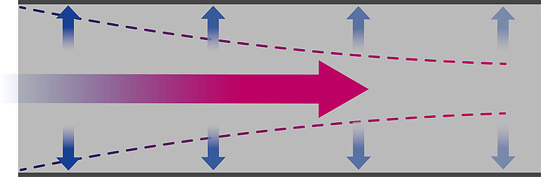
In a practical application, such as air flow through an air duct, the Bernoulli formula results in the consequence that the static pressure decreases with increasing flow velocity. This so-called Bernoulli effect is particularly relevant in the planning and design of an air-conditioning system.

Pressure Increase & Pressure Drop

Pressure Increase & Pressure Drop To optimally fulfill its specific purpose, a fan or ventilation system must set the air or other gaseous media in motion. Through this acceleration, the system thus causes a pressure increase. To achieve the pressure increase required for the application, the system, including all components (e.g., impeller, drive, air ducts, filters, etc.), must be considered as a complete system and designed accordingly.

In real-world flows, pressure losses occur thatthe fan must overcome. These are caused, for example, by (surface) friction, form resistance (round or square air duct), obstructions in the air duct (e.g., filters), deflections/branches or cross-sectional changes in the air duct, trapped contaminants, or other factors. The higher the total pressure losses in a system, the more energy the fan must consume to generate the required volume flow.

For the most efficient operation of the system, all pressure losses must be considered during the configuration or design phase and kept as low as possible. The design point should be close to the actual operating point of the system. This allows for the appropriate selection of the impeller-drive combination and the dimensioning of the system with great precision, even during the planning phase.

Fans & drives from ZIEHL-ABEGG stand for maximum efficiency and best performance in every application

Pressure-Flow Rate Correlation

When designing ventilation systems, the pressure (system pressure) in relation to the flow rate must be matched to the specific requirements of the application. Precisely matching the performance parameters, taking into account the installation conditions (e.g., length and cross-section of the air duct, installation dimensions, etc.), enables the most efficient combination of impeller, motor technology, and other system components. The sum of all pressure losses in the system as a function of the volume flow rate is graphically represented in the system characteristic curve.

  • Pressure: The system pressure of an air handling system is crucial for its ability to move air through the system, overcoming obstacles such as filters, air ducts, dampers, and air outlets. Complex systems, such as clean room ceilings or extraction systems with long duct systems and multiple filters, require higher pressures than simpler systems, such as suspended fans for barn ventilation.

    When designing the system, radial fans are particularly suitable for applications that require high pressures at low volume flows.
     
  • Volume flow: Based on the specific application requirements (e.g. room size, required air exchange rate or special process requirements), a system must move a certain amount of air or other gaseous media to optimally fulfil its function.

    When designing a system, axial fans are particularly suitable for applications that require high volume flows at comparatively low pressures.
Grafischer Vergleich von Volumenstrom-Druck-Korrelation mit beispielhaften Kennlinien eines Axialventilators und eines Radialventilators

System characteristic curve
(Example illustration)

Characteristic curve of centrifugal fan
(Example illustration)

Characteristic curve of axial fan
(Example illustration)

Practical Example


The higher the pressure drop (e.g., due to flow obstructions in the air duct, friction, or form resistance) in a system, the more energy the fan requires to achieve the desired airflow rate. From the user's perspective, it is therefore crucial to keep the pressure drop as low as possible for efficient operation.

Structural optimizations, such as the use of larger heat exchangers, shorter air ducts, or a larger pipe cross-section, can significantly reduce pressure loss. While this increases the space required and, to some extent, the construction costs of the system, it allows the system to be operated with significantly lower energy consumption. This also leads to a  reduced noise level.An optimized system configuration thus lowers operating costs over the entire service life of the system and generally leads to greater overall savings for the user.

Conclusion: To achieve the most efficient operation, optimal acoustics, and maximum cost-effectiveness of a system over its entire service life, numerous factors must be considered. This often involves finding the best compromise between the given conditions and the ideal system design from the user's perspective.

ZIEHL-ABEGG is happy to assit you with thw optimal design of your system. Contact us!

Was This Page Helpful?